
![[!]](http://resume.cemetech.net/projicon/clv2.png)
| Category: | EE & Hardware (back to list) | ||
| Project Page: | Clove 2 (Cemetech Bluetooth Dataglove) project page | ||
| Summary: | Clove 2 is a bluetooth dataglove used for one-handed typing. It uses a 31-combination finger chording design with three modes to allow every key on a standard keyboard to be typed with minimal effort. The bluetooth functionality removes the need to tether it to a computer, and since it profiles as a standard HID Keyboard, a simple translation layer to perform key remapping, sticky modifiers, and mode switching is the only software required. It consists of three components, the glove itself, the bluetooth module, and a custom charger for the Bluetooth module. | ||
| Complete: |
|
||
| Begin: | May 17, 2008 | ||
| Completed: | July 9, 2008 |
1. Overview >>
2. Photos, Videos, Details >>
3. Construction and Instructions >>
3.1. Introduction >>
3.2. Skills, Parts, and Tools >>
3.3. Constructing the Bluetooth Module >>
3.4. Constructing the Glove >>
3.5. Constructing the Charger >>
3.6. Software >>
4. More Information >>
1. Overview
The Cemetech Bluetooth Dataglove, or Clove 2 for short (pronounced like the spice) is a project to allow one-handed typing in situations where it might be impossible or impractical to use a traditional keyboard. It has been designed to allow the user to type any character from a keyboard with minimal effort, and thus is arranged with most frequently-used keys immediately accessible and less-used keys requiring two or three finger strokes to access. No character requires more than four finger combinations from any other character. It is built from easily-acquired parts, and the most complex component, the Bluetooth module, is taken from a commercial keyboard. Total cost of construction is roughly USD$60, including the glove, bluetooth module, and charger. Because all key interpretation is performed in software on the host device, remapping the keys or modifying its functionality is trivial. A sample translation application was built as a script for the Windows program AutoHotkey, but creating a translation layer or driver for any device would take minimal effort. The Bluetooth nature of the glove both allows connection to a wider range of devices than with other interfaces such as USB or PS/2, and of course makes usage more elegant by eliminating the need for a physical tether to the host.
2. Photos, Videos, Details
Click on any of the thumbnails below for the full-sized image
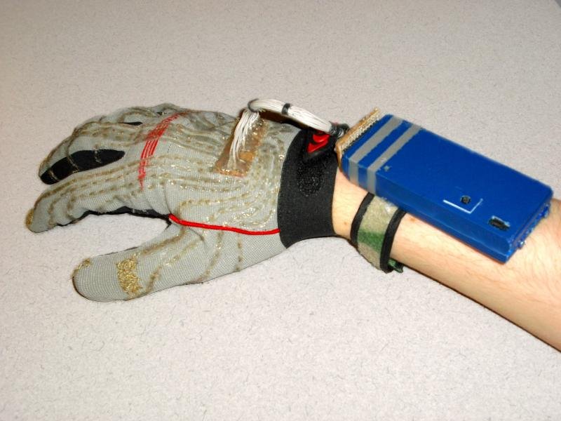


Typing on the dataglove is very similar to typing on a regular keyboard, in that every combination does something and most do different things depending on modifiers like Shift, Alt, and Ctrl. However, due to the limited number of available finger combinations, more functions must be crammed onto each key (6 on most keys). In addition to the three standard modifiers, Space has only a single function, as does the Mode key. Mode switches between alpha mode, navigation/symbol mode, and symbol/function mode. I have found that the easiest way to memorize numbers and symbols is to remember with what letter they share a finger combination. Mode toggles between the three modes, and the sample driver software I wrote provides audio cues during mode switching. Every key combo that performs an action makes a clicking noise, while modifiers each have their own tone. Enabling and disabling the glove also plays a tone sequence, so overall the glove is somewhat usable without a screen in front of the user. Alt and Ctrl are sticky: pressing Alt or Ctrl and then a key produces the same effect as holding the modifier and hitting the key on a normal keyboard. Pressing Alt and/or Ctrl a second time without a key to modify turns Alt and/or Ctrl off again. Shift operates differently, acting either as Alt and Ctrl, or if pressed twice, locking into Caps Lock. A third tap turns off Caps Lock. Below are listed all keys typable with the glove:
| # | Row | Column | Difficulty | Alpha | Shift-Alpha | Num | Shift-Num | Sym | Shift-Sym |
|---|---|---|---|---|---|---|---|---|---|
| 1 | 6 | H | ++ | y | Y | Up | Up | ||
| 2 | 7 | H | ++ | f | F | Down | Down | < | < |
| 3 | 8 | H | ++ | g | G | Right | Right | ~ | ~ |
| 4 | 9 | H | ++ | w | W | Left | Left | > | > |
| 5 | 10 | H | + | o | O | 8 | * | ; | F5 |
| 6 | 11 | H | + | i | I | 4 | $ | ? | F4 |
| 7 | 12 | H | + | n | N | 5 | % | + | F3 |
| 8 | 13 | H | + | h | H | 9 | ( | ' | F2 |
| 9 | 14 | H | 0 | Space | |||||
| 10 | 15 | H | 0 | Mode | |||||
| 11 | 16 | H | 0 | Shift | |||||
| 12 | 17 | H | 0 | Ctrl | |||||
| 13 | 14 | G | + | s | S | End | End | = | |
| 14 | 15 | G | + | r | R | Home | Home | ] | |
| 15 | 16 | G | + | d | D | 6 | ^ | [ | |
| 16 | 17 | G | + | l | L | 7 | & | _ | |
| 17 | 7 | E | +++ | z | Z | App | App | ||
| 18 | 8 | E | +++ | q | Q | Win | Win | ||
| 19 | 9 | E | ++ | j | J | Tab | Tab | ||
| 20 | 11 | E | ++ | x | X | Esc | Esc | F12 | |
| 21 | 12 | E | ++ | v | V | Enter | Enter | | | F11 |
| 22 | 13 | E | + | u | U | 3 | # | / | F1 |
| 23 | 15 | E | ++ | k | K | ` | ^ | F10 | |
| 24 | 16 | E | ++ | b | B | PgUp | PgUp | { | F9 |
| 25 | 17 | E | ++ | p | P | PgDn | DgDn | } | F8 |
| 26 | 1 | H | 0 | Alt | |||||
| 27 | 3 | H | 0 | e | E | 2 | @ | " | |
| 28 | 12 | F | + | m | M | Del | Del | - | F7 |
| 29 | 13 | F | + | c | C | BkSp | BkSp | : | F6 |
| 30 | 16 | F | 0 | t | T | 0 | ) | . | |
| 31 | 17 | F | 0 | a | A | 1 | ! | , | |
The "row" and "column" columns in the table above identify which finger and thumb/palm contacts respectively must be touched together for that particular combination. A reference as to which contacts correspond to which row/column can be found in the construction details below. The "Difficulty" column represents how hard it is for me to perform each of the finger combinations, where 0 is the easiest and the difficulty increases through + and ++ to +++ being the most difficult. Any and all of the keys in the final six columns can be modified with Ctrl and/or Alt.
3. Construction and Instructions
3.1. Introduction
The dataglove does not require great skill to build, but does require a fair bit of patience and persistence. It will be easier if you use the same materials as I did, but if you use a different keyboard, bluetooth or otherwise, you will have to derive your own keymap. I'll begin with the tools and materials needed to create the glove, module, and charger, then move on to the actual instructions and plans.
3.2. Skills, Parts, and Tools
Skills
- Basic knowledge of sewing, soldering, and hot gluing
- Ability to cut and sand plastic, especially with a Dremel
- To modify the software, basic knowledge of programming/scripting languages
- (-) Sewing needles - you should have a small one to sew into the perfboard, and a larger one for crossstitching the contacts.
- (1) Soldering iron and solder - all three parts need this.
- (1) Hot glue gun with hot glue - infinitely useful.
- (1) Dremel with cutting and sanding attachments or other plastic cutter and sander.
- (1) Scissors - to cut the thread.
- (1) Wire cutters/strippers - for all three parts.
- (1) Ohmmeter, continuity tester, or battery pack with LED to check for shorts and continuity in all three parts.
- (2) 5.25" plastic computer bay covers to create the enclosure (or other enclosure)
- (1) Dell Bluetooth keyboard, actually a rebranded Logitech keyboard, as from the Dell website
- (1) SPST subminiature switch
- (1) AWG 30 plastic-insulated wire-wrapping wire
- (1) 3.7V Li-Poly battery pack, preferably with built-in regulator/protection board
- (1) 24-pin DIP socket (for connector to dataglove)
- (-) Assorted screws, bolts, and metal contacts for securing the PCB, the charging points, and the PCB disconnector
- (-) Hot glue and solder, as above
- (1) Velcro wrist strap
- (1) Pair Craftsman Ultra Touch work gloves - should fit snugly, but finger movement should still be unhindered
- (1) Spool 234/34 4ply Conductive Thread from Sparkfun Electronics
- (-) Hot glue and solder, as above
- (-) Predrilled copper-clad perfboard with pre-cut columns, at least 8 holes by 21 holes (0.8" x 2.1"), for back of glove
- (-) Predrilled copper-clad perfboard with pre-cut columns, at least 8 holes by 14 holes (0.8" x 1.4"), to connect to Bluetooth module
- (-) IDE ribbon cable or equivalent
- (1) Spool black thread
- At least 24 pins of single-row pin header with 0.1" spacing, to be split into two 12-pin pieces
- (1) 5.25" plastic computer bay cover or other scrap plastic for body of charger
- (1) 2.0v LED
- (2) 5-ohm, 1/4- or 1/2-watt resistors
- (1) 47-ohm, 1/4-watt resistor
- (2) 2N2222 or equivalent general-purpose NPN transistors
- (2) 0.1uF/50v ceramic capacitors
- (1) 1K-ohm, 1/4-watt resistor
- (1) 1K-ohm potentiometer
- (3) 470-ohm, 1/4-watt resistors
- (1) 1N4001 diode
- (1) LM317TB, LM3940, or equivalent 3-pin voltage regulator
- (-) Assorted metal for charging contacts
- (-) Assorted plastic for PCB disconnector pin
- (1) 9V DC power supply or adapter (note polarity when soldering the DC power jack)
- (1) DC power jack
- (1) Larger piece of perfboard, at least 20x20 spaces or 2"x2", depending on how tightly you lay out components
- (-) Hot glue and solder as above
3.3. Constructing the Bluetooth Module
- The Bluetooth module is built around the PCB from a commercial bluetooth keyboard, which greatly simplifies both the hardware and software design. You can probably use any Bluetooth keyboard, but I chose a Dell Bluetooth Keyboard (actually a rebranding Logitech unit) for price, availability, and simplicity. Once you open your keyboard, you'll see that there are a series of contacts that connect the thin film contact sheets to the PCB. These are arranged in two sets, which I call rows (the more numerous set) and columns. Pressing any key connects one of the rows to one of the columns. If you use the same keyboard I used, you can use the chart below, but if you use a different keyboard, you must map your keyboard yourself. You can do this by visually tracing the thin film contact sheets, or use a continuity tester to find which keys connect which rows and columns.
 Dell Bluetooth Keyboard Keymap (14.47KB)
- Hopefully, your keyboard is powered by 2 AA or AAA batteries (~3.0v), which should make it a good candidate for a 3.7v Li-Poly battery. My keyboard had a built-in voltage regulator, but you may find that you need a resistor voltage divider (or, even better, a diode with a 0.7v drop such as a 1N4001) to drop the voltage down to 3.0V. If your keyboard requires a higher voltage, you may need to consider using two batteries in series, which will mean your charger will need to be modified accordingly (see the SHDesigns site linked below for details). Once you have extracted the PCB, find the negative and positive solder points to which the original battery pack was attached. The positive point should lead to a power switch; remove the switch and solder a 30awg wire on the far side of the switch solder points (so that the switch would no longer have done anything). Solder a second wire to the negative point. Solder your replacement SPST switch to the negative wire, and solder a second wire to the other side of the switch, leading to the negative terminal of the Li-Poly battery pack. When you finish in the next step, the circuit should be as diagrammed in the following schematic:
Bluetooth Module Power Schematic (20.71KB)
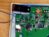
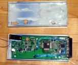
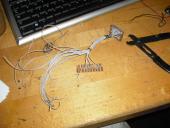
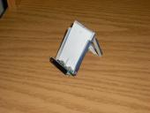
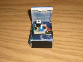
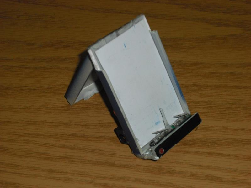
- Next, you should build the enclosure. I cut two 5.25" plastic computer bay covers so when placed together, one end of the enclosure was closed and the other was open. At the closed end of one cover piece, drill a center hole, then screw two screws through, one closer to the center on one side, one towards the edge on the other side, as you can see in the image below. You can also see where the power switch has been removed from the PCB and a replacement soldered in its place.
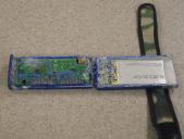
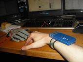
- Finally, create the connector into which the dataglove will plug. I used a 24-pin DIP IC socket, soldering 30awg wire between each of the contacts on the board and the socket. Since the Dell keyboard I used has 25 contacts, 17 rows and 8 columns, I needed to discard one, so I chose row 2. As you can see from the keymap above, it works with only a single column. I recommend soldering wires to the contacts on the PCB, routing them to whichever side of the board they need to end up on, lightly hot-gluing the socket in place at the end of the board, then soldering the wires onto the socket. The order on the socket does not matter, as long as you record it and have the dataglove's connector match the pinout on the bluetooth module. When you have finished the socket, add more hot glue to prevent shorts between adjacent contacts on the DIP socket, then put the whole module together. You may need to drill additional holes for the power switch and bluetooth connect button; I also needed an extra plastic collar around the DIP socket to make the enclosure look neater. I also drilled a final hole for the blue/orange status LED, which lights during the connection process, warns of low battery, and is off during normal operation. A final detail is the velcro wrist strap, which I hot-glued to the bottom of my module, but which you might wish to attach more securely. I'm debating adding a second strap or centering the first strap. Note the charging pins and center disconnect hole in the picture below.
Bluetooth Module Connector Mapping (25.84KB)


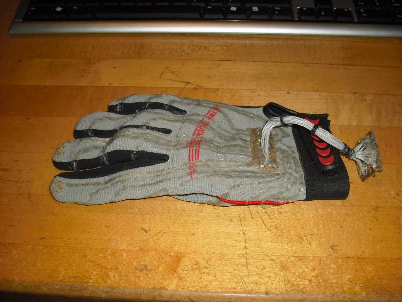
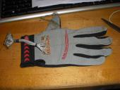
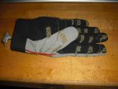
3.4. Constructing the Glove
While the glove itself is not the most challenging piece of Clove 2 to construct, it is (to my knowledge) the most novel. Two categories of steps are needed to construct the finished glove, soldering of the flexible connector between glove and bluetooth module, and the sewing of the conductive traces on the glove. I will begin with the process of soldering the connector, then move on to sewing the traces, a simple but tedious task.
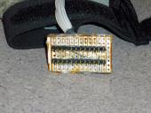
- You should have two pieces of perfboard, as indicated in the parts list above. Both should have the traces going the SHORT way, ie, parallel to the short edge and perpendicular to the long edge. For the 8x14 hole board, simple slice carefully down the center of the board, cutting every trace into two. The board should have two rows of 14 traces, each of which covers 4 holes. Begin by snapping your row of metal pins into two 12-pin pieces, and soldering them into the perfboard. They should be two holes apart, as you can see from the picture below, so that two holes remain between each pin and the outer edge of the board. The long side of the pin and the plastic piece should be on the non-copper side of the perfboard.
- Next, cut 24 pieces of wire off the IDE cable (or other ribbon cable), each of which should be at least 6 to 8 inches long, depending on how far you want the bluetooth module from the glove. Solder each of the wires into the board. In order to ensure the best connection, I stripped each piece of wire by about 1/2", inserted it into the copper-clad side right next to its corresponding pin (but on the outside, closer to the edge of the board), then brought the end back through in the same row at the outermost hole, then soldered the whole thing on the copper-clad side. when you finish, all 24 wires should be connected, and there should be no shorts between adjacent pins. Check with an ohmmeter or continuity tester if unsure. In my glove, I only needed 4 of the rows and 14 of the columns from the original keyboard, so I only bothered soldering 18 wires. You may wish to do this, or attached all 24 wires to allow for future expansion of the glove.
- Hot-glue the wires to the perfboard for extra strength, then bind the wires together right next to the perfboard. Hold off on binding the wires along the rest of their length until after you solder the board on the other end. You'll want to prepare the second piece of perfboard, 8x21 holes, as shown in the following diagram and image. Note that the traces have first been sliced down the center, then every other trace remove careful with a boxcutter. Don't cut yourself doing this; I nearly did several times.
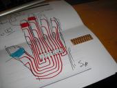
Dataglove Conductive Traces (42.61KB)
- Before you begin to solder the wires to this second board, you must do a bit of preparation beside razoring the traces. Note from the photos below that the long edges are cut halfway through the outermost hole, which will guide the thread without requiring the thread to be passed through a hole. Use a dremel, sanding block, Xacto knife, or your tool of choice to trim the long edges of the board. Now you can begin to attach the wires. I used a piece of solder to temporarily bind the wires near this second board to get a sense of the required length, then cut the wires, stripped 1/2", passed the end through the hole closest to the center (copper-clad side), and then up again at the next hole towards the edge, as with the perfboard on the other end. I then trimmed, soldered, and hot glued the wires in place. It is in this step that you must make sure the row and column order matches the layout in the Conductive Traces diagram linked above. Once you have soldered and glued all 18 or 24 wires, use the black thread (or your preferred method) to bind the wires at several places along the cables's length. Keep in mind that the cable will need to flex as you move your hand, so try to aim for a compromise between strength and flexibility.
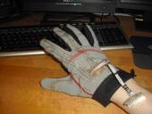
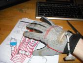
- Now begins the least engineering-oriented part, sewing the glove. The first step is to use a thin needle with a small hole to fasten the perfboard to the back of the dataglove. A small note: I made a right-handed glove. If you wish to make a left-handed glove, you must reverse everything in the Dataglove Conductive Traces diagram. Other than that, the instructions remain the same. USe the black thread to sew in and out of the holes where the traces have been removed. Do not cross any of the traces with the thread. When you finish, knot the thread inside the glove, cut, and secure with a dab of hot glue. You may wish to do each corner as a separate thread, and perhaps sew in the middle as well, for the most robust and strong attachment. With this in place, the only remaining step is to use the conductive thread to make the glove traces and contacts. In the diagram below, note the small loops of black thread. I went through several (~6-8) times to ensure the board would not come loose.
- Every trace is sewn in essentially the same way. I recommend starting with the contacts on the fingernails of the index and middle fingers, move on to the twelve finger contacts, then finish with the three thumb contacts and the palm contact. Begin by figuring out where the contact should end and the trace from the contact to the perfboard should start. Start sewing here, and sew the thread alternately in and out of the fabric until you reach the perfboard. It should follow the rough path laid out in the Conductive Traces diagram above. Several notes: first, the thread frays very easily, so try not to undo too much and redo. If you must, use a new piece of thread, for as the thread frays, its conductivity decreases dramatically. Also, it is vitally important that each thread not touch any of its neighbors, as shorts will render the glove useless (since multiple contacts will be connected). Use an ohmmeter, a continuity tester, or even a battery and an LED to make sure adjacent threads are not electrically connected. Also, to ensure that the tension in the thread is correct, I found it helpful to sew the traces while wearing the glove. If you'd rather not stick yourself every once in a while or can't sew left handed, at least pull the fingers and cuff of the glove every once in a while to stretch the glove so there's some slight slack in the thread when you let go. Once you reach the perfboard, switch to a needle small enough to fit smoothly through the holes in the perfboard. Sew up through the first hole in, then down at the edge in the semicircle you created by shaving the long edges of the PCB, and repeat two or three times. Make sure the thread is tight enough to make a good connection to the copper trace, which you should verify with your handy continuity tester / ohmmeter / LED and battery, then dab on some hot glue to hold the thread in place on both the inside and top of the perfboard, and cut the thread. Now you should sew the contact on the other end of the thread. If you examine my photos below closely, you'll see I sewed in X shapes, which seems to provide the most reliable contacts. You'll have to cut the thread off the spool before beginning this part, so make sure you leave yourself enough length of thread. When you finish, bring the thread to the inside, dab on some glue, and cut the thread. If you're really thorough, loose the end along the trace towards the perfboard. The final step for each trace is to put on a very thin line of hot glue on the thread. Pull the tip of the glue gun along the thread, barely pressing down on the trigger. You might need to go over twice or three times to get enough on to cover the thread, but it should remain thin and flexible enough not to hinder movement. If you're worried about shorts to other threads on the inside, you can repeat the process inside the glove. Do this again for all the other traces, and you'll be done with the glove. A final note: while I presented a recommended contact placement that works well for my hands, it might not work well for yours. Consult the 31-combination chart at the top of this page and make sure you can complete all the combinations comfortably. If not, you may wish to change where the contacts are placed or how the glove is mapped.


3.5. Constructing the Charger
The charging circuit in the charging dock for Clove 2 is fairly simple, and based on an original charger design by Scott Henion of SHDesigns, designed in 2003. The circuit for Clove 2 is designed to work with a 3.7v LiPoly battery pack under no load, as the original keyboard used was designed for a pair of AA batteries. The charging circuit will properly charge the battery pack, varying current so that it remains full while protecting against overcharging. To create the charging dock:
- Begin by creating the circuit board, as per the schematic and layout below. Note in the layout that the red double lines indicate where you should cut the perfboard traces to break the circuit (check with a continuity tester that the connection is actually broken). Also be aware that the voltage regulator and transistors can be damaged by heat, so try to minimize the solder time for these components. In my design, I brought the LED off-board so I could mount it on the front of my charging dock, but you may wish to keep it on the PCB.
Dataglove Charger Schematic (25.63KB)
Dataglove Charger Layout (32.65KB)
- Next, create the dock structure. It should have two contacts to touch the two charge points on the bottom of the bluetooth module, and a long plastic pin to fit into the bluetooth module's disconnect hole. I used more 5.25" plastic drive bays to build my dock, but you may wish to use other materials as per personal preference.

- Finally, mount the PCB into the dock (I hot-glued it to the back of the unit), and solder the output wires onto the charging contacts. Make sure that the polarity matches the polarity of the bluetooth module; for my design, the negative contact was closer to the center on one side, and the positive contact was near the edge on the other side. Make sure that the plastic disconnect properly opens the normally-closed switch inside the bluetooth module. Mount the DC power jack, solder it on, then plug it into the 9v adapter and connect a multimeter to the output contacts in the dock. Adjust the multimeter until the potential across the output pins is exactly 4.2v, the correct charging voltage for a 3.7v Lithium Polymer battery.


3.6. Software
As detailed above, the software that translates keypresses detected by the glove into keypresses on the host system is fairly simple. I wrote a Windows script for a program called AutoHotkey, freeware for most versions of Windows (but not *nix or Mac OS). I plan to eventually create ports to (almost definitely) *nix and (possibly) Mac OS. The source code of the script can be downloaded at the link below. Note that while this will work properly only with the module from the Dell Bluetooth Keyboard that I used, a few simple edits to correct the keys corresponding to each of the 31 finger combinations will suffice to modify it for any keyboard. To activate or deactive the dataglove/translation layer, press ctrl-alt-C.
![]() clove2.ahk - Plaintext Clove 2 translation script for AutoHotkey (AHK/TXT, 4.76KB)
clove2.ahk - Plaintext Clove 2 translation script for AutoHotkey (AHK/TXT, 4.76KB)
4. More Information
Please be advised that the Clove 2 Bluetooth Dataglove is a personal project, not a commercial offering. As such, no warranty is made to its fitness or appropriateness for any application or use. All information in this page from other sources has been properly attributed to the best of my knowledge, and if I am in error, please inform me at clove2@cemeetech.net, replacing the double e with a single e. Of course, as this page contains instructions for replicating my work, I and Cemetech disclaim any and all rsponsibility for damage, injury, etc resulting from following the instructions on this page or anywhere else on this site. If you try to make your own dataglove, you claim all responsibility for injury, damage, etc resulting from building or using the device. A bit of common sense, don't use one while walking around unless you're moderately confident of your ability not to run into cars or walls while trying to type one-handed.
With all that boilerplate out of the way, please feel free to contact me about this project for more pictures, instructions, feedback, comments, or help with your own version. Your best bet is to write a post on the forums here, but failing that, try me at clove2@cemeetech.net, replacing the double e with a single e. Hope you enjoyed this!
Unless otherwise noted, all schematics, plans, instructions, and information on this page (c) 2006-2008 Christopher Mitchell (Kerm Martian) and Cemetech. Except for fair use, this page or its embedded and attached information may not be reproduced without proper attribution to the author or the express written permission of the author.
Advertisement