
| Category: | EE & Hardware (back to list) | ||
| Project Page: | Graphing Calculator Whack-a-Mole: ArTICL and MSP432 project page | ||
| Summary: | |||
| Complete: |
|
||
| Begin: | May 15, 2015 | ||
| Completed: | September 26, 2015 |
Project Participants:
Christopher Mitchell ("Kerm Martian")
Tim Keller ("geekboy1011")
In September 2015, administrators and staff of Cemetech attended World Maker Faire in New York City for the fourth year in a row. We wanted to create a fun demo combining a TI graphing calculator and an MSP432 Launchpad development board controlling some hardware. We hit on the idea of a light-based Whack-a-Mole game, where the calculator would light up on of nine target circles on a physical Whack-a-Mole board as well as on a similar board displayed on its screen. Players would have to quickly block the light in that target from reaching a CDS cell light sensor using a mallet (or, as we eventually used, a roll of electrical tape). The rules would be simple:
- Players would get points for how fast they "whacked" the correct "mole"
- The player would get three lives, losing a life each time the player hit the wrong target or didn't hit any target in the allotted time.
- The game would end after the player lost all three lives.
Satisfied that we had dreamed up a fun demo, we set to work on the electronics, the software, and the hardware for the game. If you're mostly interested in photos and videos of the finished product, you can jump straight to that section.
1. Planning the Whack-a-Mole Game
We started from the idea that we wanted a project that would use elaborate external hardware well-suited to the many GPIO pins available on the MSP432. Whack-a-Mole seemed like a reasonable idea, and a previous CBL2-based Whack-a-Mole game from Cemetech administrator Shaun "Merthsoft" McFall that used the Vernier light sensor sold to work with TI graphing calculators provided further inspiration. The first ideas for the game looked something like the following sketch. The horizontal and vertical portions were envisioned to be boards of some sort, the squares on the horizontal portion are plexiglass, and the calculator and MSP432 are mounted next to explanatory text. We decided to use 5V RGB LEDs for the light sources, LEDs for which an analog voltage between 0V and 5V would provide an intensity between off and full brightness for each of the red, green, and blue elements. To detect the light (and interruption of the light) from the LEDs, we chose to use CDS cells, which vary their resistance proportionally with how much light is striking them.
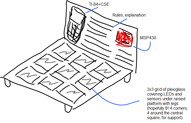
We refined the idea to have separate vertical and horizontal portions to make the game more robust to the kids who would no doubt be whacking at the display during Maker Faire, connected by a pigtail of flexible wiring. We also revised the innards of the horizontal "whacking" section to be a wooden sandwich with no plexiglass, containing the LEDs and CDS sensors:
Note: cross-sectional view. Each === layer is particle board

==============                             ============= Top layer
====   ---|| CDS     v-Painted?         LED  (__--- ==== Middle layer
======================================================== Bottom layer2. Designing the Driver Circuit
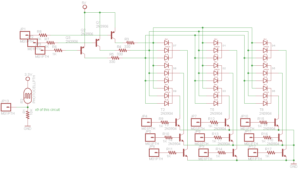
We knew our Whack-a-Mole game would need at least 9 RGB LEDs, one for each of the nine targets in the game, and 9 CDS cells, one for each LED. In the worst case, that would be 9*3=27 PWM-capable output pins for the LEDs, and an additional 9 analog input pins for the CDS cells. This number was understandably unacceptably large, so we looked for ways to reduce the pincount. We knew that we only would need to light up one RGB LED at a time, corresponding to the target currently active in the 3x3 grid. Our RGB LEDs were common-cathode, so we designed the scheme shown in the schematic below that allowed us to control the LEDs with 3 PWM-capable outputs and 9 additional digital outputs. An NPN transistor was placed on the cathode of each LED, used to select the LED to be illuminated. The red anode pins of each RGB LED were connected together, controlled by a PNP transistor connected to a PWM-capable MSP432 pin: the red component of the select LED could thus be controlled. The green and blue anodes were similarly connected together, for a total of 12 output pins to control the LEDs.


Click any image to enlarge
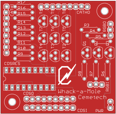
Besides the RGB LED control circuitry, I added nine voltage dividers for the CDS cells to the board. Because we weren't sure what resistor value would be ideal for our indirect sunlight-lit Maker Faire booth, we decided to use an IC socket on the board for the CDS cells' resistors. On a train to visit Tim, I designed a full schematic, and on my way home, I created and routed a PCB and ordered it through DirtyPCB.

Click any image to enlarge


Click any image to enlarge
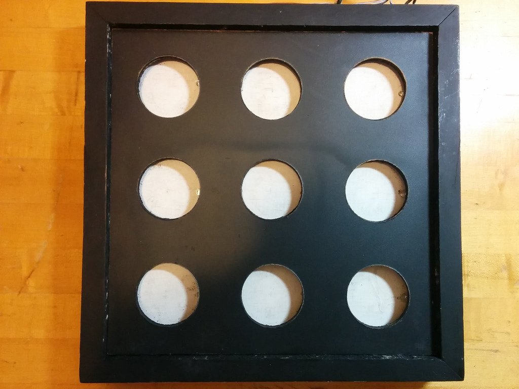
3. Building the "Whacking" Area
The "whacking" or target area of the Whack-a-Mole game was to consist of nine circles in a 3x3 grid, designed to be sturdy enough to hold up to assault from thousands of visitors to World Maker Faire. We designed a light-based Whack-a-Mole game, which originally meant that players would place their hands over the targets to register a whack. However, we decided that that would not work well in the highly-variable illumination at Maker Faire, so we settled on a scheme where players would interrupt the LEDs' beams insted. Each CDS cell and LED was to be covered by a black-painted top layer that would prevent most direct ambient light from reaching the CDS cells. In addition, framing was placed between each target to minimize light leakage between adjacent targets. The woodworking for the case was completed by Tim and his carpenter father, producing a spiffy, professional-looking case that fit together well and into which a cover could quickly be inserted or removed for fixes or to show what hardware was making the game work.
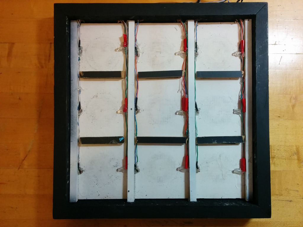
The process of soldering the LEDs and CDS cells together, insulating their leads, and hotgluing them into the display was arduous, many hours long, and took place during a marathon viewing of Portlandia episodes. Each LED's red lead had to be connected to each other LED's red lead; green and blue leads also had to be put in parallel. Nine separate cathode wires were also pulled out of the target case. The nine separate CDS cell cathodes were also broken out to wires, while the anodes of all the CDS cells were connected together to a common VCC wire. At the end, two hefty pigtails protruded from the target case, as shown below: one for LED wires, the other for CDS cell wires. As I worked, I tested each LED and CDS cell with the developing TI-BASIC Whack-a-Mole game and completed MSP432 firmware (as discussed in the next two sections). The rightmost photo below shows the completed game being tested.


Click any image to enlarge
4. The MSP432 Firmware
Tim was assigned to use ArTICL to create an MSP432 firmware that would control the LEDs and poll the CDS cells on behalf of the graphing calculator. The easiest way to use ArTICL is to have the calculator send lists (arrays) containing one or more numbers to the MSP432, and request lists back from the MSP432. The preliminary API that we designed looked something like the following:
-
Send({N, R, G, B}): Turn off all 9 RGB cathode transistors, turn on the single Nth RGB cathode transistor (1-9), set PWM anode transistor lines to R=R, G=G, B=B. -
Send({0}): Turn all cathode transistors off. -
Get({N}): Get the analog value of the Nth (1-9) CDS cell, on a scale from 0-1023 -
Get({10}): Get the analog value of all 9 CDS cells as a 9-element list (array)
Realizing that the latter two commands would require sending a number first via Send() and then using Get(), we simplified the API, removing one command:
-
Send({N, R, G, B}): Turn off all 9 RGB cathode transistors, turn on the single Nth RGB cathode transistor (1-9), set PWM anode transistor lines to R=R, G=G, B=B. If N=0, just turn everything off. -
Send({0}): Turn all cathode transistors off. -
Get(): Get the analog value of all 9 CDS cells as a 9-element list (array)
With this API, it would be easy to both see if the player had triggered the correct target by blocking the beam from the currently-illuminated LED, and if the player had covered the wrong target, blocking the ambient light from reaching another light sensor. In fact, as shown in the next section, the ability to do vectorized math with lists in the TI-84 Plus C Silver Edition's TI-BASIC language (that is, perform simultaneous operations on every element of a list) make this a particularly efficient way to check all of the CDS cells repeatedly.
The remainder of this section provides more detail on how commands sent from the calculator are processed by the ArTICL library on the MSP432. Note that debug statements and some defensive coding sections have been removed for simplicity. The full source of the firmware can be found on GitHub.
4.1. Sending Data to the MSP432
When the CBL2 class within ArTICL receives a type variable corresponding to a TI-OS variable type, plus a data array holding the bytes for that variable received from the calculator. This code first checks if the data is a list, and if so, if it's a one-element or four-element list. If it is, it acts accordingly, using realToLong8x() from ArTICL to pull list elements out of the received list.
If the list received has 1 element, then the only valid command it can be from the spec is
  if (type != 0x5D) { //VarTypes82::VarRList) ???
    return -1;  //If you are not a list we do not want you ABORT
  }
  int list_len = data[0] | (data[1] << 8);
  switch(list_len) {
    case 1:{			// One-element list
        int value = (int)TIVar::realToLong8x(&data[2], model);  // Get element
        switch(value){
            case 0:{  // Turns off all LEDS
                turnOffAllRGBLEDs();
                return 0;
            }
        }
    }
Otherwise, the MSp432 checks if the list received has four elements, in which case it could be the command to turn one of the LEDs on and set it to a specific RGB color. If the list has four elements, the first element is pulled out and used to figure out which LED to turn on, then the remaining three elements are used for the red, green, and blue values.
    case 4:{  // RGB Control structure (four-element list)
             // {N,R,G,B} Where N is LED and RGB=Analog Values for each color

        turnOffAllRGBLEDs();  //First we turn off the multiplexer

        int Offset = 2;  //Start us after the size bytes
        int NewLed = (int)TIVar::realToLong8x(&data[Offset], model);  // Get element

        Offset += TIVar::sizeOfReal(model);
        int val_red = (int)TIVar::realToLong8x(&data[Offset], model);
        Offset += TIVar::sizeOfReal(model);
        int val_green = (int)TIVar::realToLong8x(&data[Offset], model);
        Offset += TIVar::sizeOfReal(model);
        int val_blue = (int)TIVar::realToLong8x(&data[Offset], model);

        analogWrite(RGB_Red, 255 - val_red);
        analogWrite(RGB_Green, 255 - val_green);
        analogWrite(RGB_Blue, 255 - val_blue);
        SetRgbActive(NewLed);  //Turn on the new LED
        return 0;
    }
  }
4.2. Requesting Data from the MSP432
When the calculator issues a Get() request, ArTICL's CBL2 class triggers a different callback, this one responsible for filling in the body of the variable that the calculator is requesting so that ArTICL may send it. From the Whack-a-Mole demo, the only data the MSP432 can send back to the calculator is the analog values of the 9 CDS cell light sensors. Therefore, when the callback triggers, the firmware builds an ANALOG_PIN_COUNT (i.e., 9)-element list, then uses the
    // Compose the VAR header
  *datalen = 2 + TIVar::sizeOfReal(model) * ANALOG_PIN_COUNT;
  TIVar::intToSizeWord(*datalen, &header[0]);	// Two bytes for the element count, ANALOG_PIN_COUNT Reals
                                                // This sets header[0] and header[1]
  header[2] = 0x04;				// RealList (if you're a TI-85. Bleh.)
  header[3] = 0x01;				// Name length
  header[4] = 0x41;				// "A", as per "standard" See http://www.cemetech.net/forum/viewtopic.php?p=224739#224739
  header[5] = 0x00;				// Zero terminator (remainder of header is ignored)
  *headerlen = 11;

  // Compose the body of the variable
  data[0] = ANALOG_PIN_COUNT;
  data[1] = 0;
  int offset = 2;
  for(int i = 0; i < ANALOG_PIN_COUNT; i++) {
	long value = analogRead(analogPins[i]);
	// Convert the value, get the length of the inserted data or -1 for failure
	int rval = TIVar::longToReal8x(value, &data[offset], model);
	if (rval < 0) {
		return -1;
	}
	offset += rval;
  }
This firmware as presented, with callback functions that set up the LEDs when a list is received and return the status of the CDS cells when a list is requested, is enough to allow the calculator to interface with the hardware. With the ability to turn the LEDs on and off and
5. The Calculator Software
The calculator-side software for the Whack-a-Mole game was written in hybrid TI-BASIC, that is, TI-BASIC that uses z80 assembly libraries for more functionality. In this case, the ASM library used was Doors CSE 8 for the TI-84 Plus C Silver Edition. The xLIBC library gives programmers many more options for graphics that the built-in TI-OS, including fast lines and filled shapes, sprites, colored text, and more. For the Whack-a-Mole game, we used the xLIBC functions to quickly draw the Whack-a-Mole board, including rendering a colored circle for the currently-active target. We used the built-in TI-BASIC
The calculator software, MSPWHACK, is 147 lines of TI-BASIC long, and can be found in this project's GitHub repository. The code will not be presented in full here, but the program's overall flow deserves examination, as does its handling of a few things like checking the value of the CDS cells. The outline of the game's main loop is something like the following:
- Set number of lives to 3
- Draw the game grid; use the
Send({0})command to shut off all LEDs - Until the user presses [CLEAR] to quit or all three lives are used:
- Pick an LED to light up, and a random one of 8 primary colors in which to light it
- Use the
Send({N, R, G, B})command to light that LED. Read the CDS cells withGet()to fetch the initial light level at each sensor, repeating the read 4 times and averaging the results. - Start a timer. Until the timer runs out, check the keyboard, and poll the CDS cells with
Get() - If the light level hitting any sensor changes by at least 100 (that is, 10% of the 0-1024 scale for
analogRead()):- If it's the correct target, increase the score by one, and restart the loop
- Otherwise, decrement the number of lives left, and restart the loop
- If the user pressed [CLEAR], end the game. If the timer ran out, decrement the number of lives left, and restart the loop
- Display the current score. Compare the score to the high score, and if it's a new high score, alert the user and store the new high score.
The optimized TI-BASIC code that implements the outline above is convoluted, but mathematically straightforward. The most unusual section of code is the one that checks if any CDS cells' incident light level has changed by more than 10%. First, we must get the initial value read for each CDS cell, and to smooth out any noise, we take the average of four measurements. That averaged list of 9 elements is stored on the calculator in list L4
:9->dim(L4
:Fill(0,L4
:For(X,1,4
:Get(L3
:L3+L4->L4
:End
:L4/4->L4
We create a 9-element list, fill it with zeroes, then get a 9-element list of the current CDS cell readings and add it to that list four times. Dividing the list by 4 (the number of samples aggregated) gives the average value. Because TI-BASIC can perform vectorized operations, a loop to add and divide each element individually is not needed, as it might be in another language.
The code to determine if a CDS cell has been interrupted looks a little more complex. It uses a few variables: L3 is used to store a temporary list of values read from the CDS cells' current state, L4 still holds the original average from the CDS cells, D contains the index of the target currently lighted (between 1 and 9), and T holds the threshold used to determine if a CDS cell has indeed been covered.
:Get(L3
:max(abs(L3-L4
:If T<Ans
:D=max(seq(X(Ans=abs(L3(X)-L4(X))),X,1,dim(L3->M
First, the new set of 9 CDS cell values is read into L3 using the Get() command. Then, the amount that the CDS cell that has changed the most from the initial readings has changed is computed. L3-L4 returns a signed list of how much each CDS cell's value has changed from the initial reading, and max(abs() selects the one with the largest magnitude. If that largest value is greater than the threshold T (that is, max(abs(L3-L4)) > T), then a CDS cell has been covered. The final, long line in the code above determines if it was the CDS cell for the correct (lighted) target.
Let's work this from the inside out. First, (Ans=abs(L3(X)-L4(X))) checks if element X (for X between 1 and 9) is the element that had the maximum value still in Ans, stored from the expression max(abs(L3-L4)). That expression evaluates to 1 if it's true, and 0 if it's false. By multiplying by X, we get either the index of the most-changed CDS cell (X*1), or zero (X*0). Next, we plug all of the values from 1 to 9 into X using the seq() command. seq(expr, variable, start, end) creates a list formed by plugging values from start to end into variable and repeatedly evaluating expr. In this case, it will produce a list that is all zeroes with a single non-zero element, holding the index of the CDS cell that most changed since the initial reading was taken. finally, D=max(seq(...)) takes the maximum (which is necessarily the index of the most-changed CDS cell) and compares it to D, storing the result in M.
The upshot of this is that we can very quickly set M to 1 if the player covered the correct CDS cell, or 0 if the player covered the incorrect CDS cell. The remainder of the code is relatively straightforward, and the curious programmer can use SourceCoder to explore it.
6. The Finished Product: Live at World Maker Faire 2015
The finished Whack-a-Mole game was a big hit at World Maker Faire 2015 among visitors young and old. We were surprised to find that it performed admirably as the ambient sunlight changed throughout the days, although it was necessary for our visitors to use a roll of electrical tape as a mallet to block the LEDs' light from the CDS cells effectively enough for reliable operation. We're hoping to show the Whack-a-Mole demo at Texas Instruments' T^3 2016 conference this February to show teachers the kinds of STEM activities they can create with graphing calculators and electronics.


Advertisement